


Binocular Camera Module
Binocular Camera Modules for Dual-Image Capture and OEM Vision Systems
Binocular camera modules combine two coordinated imaging channels for projects that need dual-view capture, RGB and infrared imaging, stereo-vision evaluation, or integrated recognition functions. SincereFirst’s current category direction is primarily built around USB-based dual-camera modules for PCs, embedded hosts, and smart devices, while selected designs can also use UART or combined USB and UART communication. The correct configuration depends on the imaging task, algorithm path, working distance, interface, and mechanical structure required by the final device.
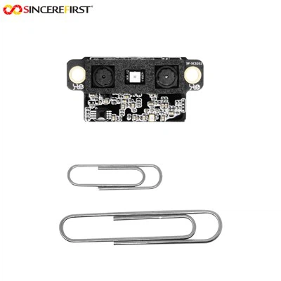


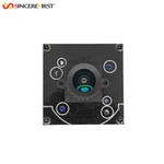
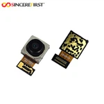
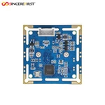
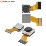
A binocular camera module places two cameras in one controlled assembly so they can capture coordinated images from different viewpoints or different spectral channels. Depending on the design, the module may provide two image streams for host-side processing, combine RGB and infrared cameras for recognition, or integrate a processing board for selected face-recognition or liveness-detection functions. A binocular module should not be assumed to output depth maps, point clouds, or recognition results unless those functions are confirmed for the specific model and software path.
Why Choose a Binocular Camera Module?
Two Imaging Channels in One Assembly
A coordinated dual-camera structure supports left and right viewpoints or RGB and infrared capture without requiring the device team to position two unrelated camera modules independently.
01
More Stable Optical and Mechanical Relationships
A shared module structure makes the camera spacing, viewing overlap, mounting position, and cable routing easier to control during device integration and repeat sample evaluation.
02
A Practical Starting Point for Stereo and Recognition Projects
The dual-image input can support stereo vision, depth-related processing, face recognition, or liveness evaluation when the required algorithms, calibration, and processing resources are available.
03
Flexible Integration Paths for Different Devices
USB is the primary host-side path in this category. Selected modules can also use UART or combined USB and UART communication when the device needs command control, local processing, or an integrated recognition board.
04
OEM Configuration Around the Final Product
Sensor pairing, lens angle, camera spacing, infrared lighting, board layout, connector direction, and enclosure structure can be reviewed together instead of treating the two cameras as isolated components.
05
How to Choose a Binocular Camera Module
Start with the Required Dual-Camera Function
Define whether the device needs two visible-light views, RGB and infrared capture, host-side stereo processing, face recognition, liveness detection, or another dual-image function. The phrase “binocular camera” describes the hardware arrangement, not a guaranteed algorithm output.
Match the Two Imaging Channels
Confirm the sensor type, resolution, exposure behavior, lens direction, image orientation, and whether both channels must use matched sensors or different RGB and infrared configurations. Image consistency requirements should be defined before sampling.
Define Baseline, Field-of-View Overlap, and Working Distance
The camera spacing and overlapping field of view affect whether both channels can observe the same target at the intended distance. Provide the target size, nearest and farthest distance, required scene coverage, and available mechanical width.
Confirm Synchronization, Calibration, and Processing
Determine whether the project needs simultaneous capture, factory calibration data, host-side calibration, a depth algorithm, a recognition algorithm, or an integrated processing board. Exact synchronization accuracy, depth output, point-cloud output, or recognition performance must be confirmed by model.
Select the Interface and Host Path
USB2.0 is the main direction in the current category. Selected products also support UART or USB and UART combinations. Confirm the host platform, output mode, command protocol, bandwidth, cable length, power input, operating system, and application software before sample selection.
Plan Lighting and Mechanical Integration
RGB and infrared projects may require optical filters, an infrared illuminator, or controlled lighting. Confirm module dimensions, camera spacing, mounting points, cable and connector direction, board placement, heat, lens clearance, and final enclosure protection.
Choose a Binocular Camera Module by Application

Face Recognition and Access Control
RGB and infrared dual-camera configurations can provide image input for selected face-recognition and liveness-detection systems. The recognition algorithm, target distance, lighting, infrared illumination, interface protocol, and processing path should be confirmed before module selection.

Smart Door Locks and Video Intercom Devices
Compact binocular modules can support identity imaging, visitor capture, and infrared-assisted image acquisition in smart locks and video intercom products. Camera spacing, module width, lens angle, infrared-lighting position, power input, and enclosure structure should be evaluated together.

Robot Obstacle Perception
Synchronized dual-camera images can provide visual input for obstacle-distance estimation, navigation, and scene interaction when combined with a suitable stereo-vision algorithm. Baseline distance, field-of-view overlap, target range, synchronization, calibration, and host processing capability are key selection factors.

Stereo Measurement and 3D Development
Binocular modules can be used as image-acquisition hardware for disparity calculation, depth evaluation, dimensional analysis, or 3D reconstruction development. The project should define whether it requires synchronized raw streams, calibration parameters, depth data, or a complete algorithm output.
Custom Binocular Camera Module Options
Dual-Camera Imaging Configuration
Sensor type, resolution, RGB and infrared pairing, lens angle, optical filters, image orientation, camera spacing, and infrared-lighting direction can be evaluated according to the target and working distance.
Interface, Processing, and Software Path
USB, UART, combined USB and UART communication, control protocol, image output, integrated processing, firmware functions, image tuning, calibration data, and algorithm integration can be discussed where supported by the selected platform.
Mechanical and Electrical Integration
PCB dimensions, dual-camera layout, cable length, connector type, mounting points, power input, microphone or speaker integration, and enclosure structure can be adjusted where applicable and subject to sample validation.
Engineering and Manufacturing Support
SincereFirst supports binocular camera module projects with more than 30 years of camera module manufacturing experience, Class 10 / Class 100 dust-free COB workshops, Active Alignment manufacturing processes, and OEM / ODM development support. The project path focuses on the complete dual-camera imaging and integration requirement rather than isolated sensor specifications.
1. Requirement Review
Review the application, dual-camera function, target distance, lighting, host platform, algorithm path, interface, power, mechanical space, and expected production stage.
2. Module Recommendation or Design Proposal
Recommend an available USB-oriented binocular direction or define a custom RGB, infrared, interface, processing, and structural proposal based on the confirmed project requirements.
3. Sample Evaluation
Test image consistency, viewing overlap, synchronization behavior, lighting, interface communication, algorithm workflow, cable routing, and mechanical installation in the real device environment.
4. Adjustment and Confirmation
Review sensor, lens, baseline, infrared lighting, interface, protocol, firmware, calibration, PCB, cable, connector, or enclosure adjustments where applicable.
5. Production Support
Support the confirmed configuration toward repeatable production and supply planning after sample performance and project requirements have been approved.


Certifications
Available public support includes ISO quality system information and product compliance directions such as RoHS, REACH, CE and FCC where applicable. Final certification or compliance requirements should be confirmed according to the product model and target market.
FAQ
Q: What is the difference between a binocular camera module and a standard single-camera module?
A: A binocular camera module uses two coordinated imaging channels, while a standard single-camera module captures one viewpoint or spectral channel. The dual-camera structure can provide the image input needed for stereo, RGB and infrared, recognition, or comparison-based processing.
Q: Is a binocular camera module the same as installing two separate camera modules?
A: Not necessarily. Two separate cameras can be combined by the device developer, but their spacing, alignment, synchronization, calibration, cables, and mounting must be controlled independently. A binocular module provides a more integrated starting structure, although the exact calibration and synchronization capability still depends on the model.
Q: Does every binocular camera module output depth maps or point clouds?
A: No. Some modules provide dual image streams for host-side processing, while selected systems may include calibration or integrated algorithms. Depth maps, point clouds, ranging accuracy, and 3D output must be confirmed for the exact hardware and software configuration.
Q: Is this category limited to USB binocular camera modules?
A: A: No. USB is the primary direction in the current category, especially USB2.0 dual-camera modules. Selected designs can also use UART or combined USB and UART communication for control or integrated recognition functions.
Q: What should be confirmed for face recognition or liveness detection?
A: Confirm whether the required algorithm is host-side or integrated, which RGB or infrared inputs it needs, the recognition distance, lighting conditions, enrollment capacity, protocol, processing hardware, and validation method. These functions are not universal features of every binocular module.
Q: Can the baseline, sensors, infrared lighting, and structure be customized?
A: These directions can be evaluated according to project requirements. Sensor pairing, camera spacing, lens angle, optical filters, infrared illumination, PCB, cable, connector, power, and enclosure structure remain subject to platform feasibility and sample validation.
Q: What information should I provide before requesting a sample?
A: Please provide the application, required dual-camera function, target distance, field of view, camera spacing or space limit, sensor and resolution direction, RGB or infrared requirement, interface, algorithm or output requirement, lighting, power, host platform, mechanical layout, expected quantity, and sample test plan.
Need Help Selecting a Binocular Camera Module?
Share your application, dual-camera function, target distance, RGB or infrared requirement, interface, algorithm path, processing location, mechanical space, power, expected quantity, and sample test conditions. SincereFirst can help evaluate a standard USB-oriented module direction or a custom binocular camera development path.