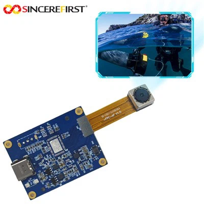
Hey there! As a supplier of the OV7725 Camera Module, I've had my fair share of experience with this nifty little device. In this blog, I'm gonna walk you through how to control the OV7725 Camera Module using a microcontroller. Whether you're a hobbyist looking to build a cool project or a professional in need of a reliable camera solution, this guide will help you get the most out of your OV7725 module.


Understanding the OV7725 Camera Module
First things first, let's get to know the OV7725. It's a low - cost, high - performance camera module that offers VGA (640x480) resolution. It's packed with features like automatic exposure control, automatic gain control, and automatic white balance, which make it a great choice for a wide range of applications, from surveillance systems to robotics.
The OV7725 communicates with the microcontroller through a combination of I2C (Inter - Integrated Circuit) and parallel interfaces. The I2C interface is used to configure the camera settings, such as resolution, frame rate, and image quality. The parallel interface is then used to transfer the captured image data from the camera to the microcontroller.
Choosing the Right Microcontroller
When it comes to choosing a microcontroller to control the OV7725, there are a few things to consider. You need a microcontroller that has enough processing power to handle the data transfer and image processing tasks. It should also have an I2C interface for configuring the camera and enough GPIO (General - Purpose Input/Output) pins to handle the parallel data transfer.
Some popular microcontrollers that work well with the OV7725 include the Arduino Due, Raspberry Pi, and STM32 series. The Arduino Due is a great option for beginners because it's easy to use and has a large community of users who can provide support. The Raspberry Pi, on the other hand, offers more processing power and can run a full - fledged operating system, which is useful if you need to perform more complex image processing tasks. The STM32 series is known for its high performance and low power consumption, making it a good choice for battery - powered applications.
Connecting the OV7725 to the Microcontroller
Once you've chosen your microcontroller, it's time to connect the OV7725 to it. Here's a basic wiring guide:
- Power Supply: Connect the VDD pin of the OV7725 to the 3.3V power supply of the microcontroller. Make sure to also connect the GND pin to the ground of the microcontroller.
- I2C Interface: Connect the SCL (Serial Clock) and SDA (Serial Data) pins of the OV7725 to the corresponding I2C pins on the microcontroller. For example, on an Arduino Due, the SCL pin is A5 and the SDA pin is A4.
- Parallel Interface: Connect the data lines (D0 - D7) of the OV7725 to the GPIO pins of the microcontroller. You'll also need to connect the HREF, VSYNC, and PCLK pins, which are used to synchronize the data transfer.
Configuring the OV7725 using I2C
After connecting the OV7725 to the microcontroller, the next step is to configure it using the I2C interface. The OV7725 has a set of registers that can be accessed and modified via I2C to change its settings.
Here's a simple example of how to configure the OV7725 using the Arduino IDE:
#include <Wire.h>

#define OV7725_ADDR 0x21

void setup() {
  Wire.begin();
  Serial.begin(9600);

  // Configure the OV7725
  Wire.beginTransmission(OV7725_ADDR);
  Wire.write(0x12); // Register address
  Wire.write(0x04); // Register value
  Wire.endTransmission();

  Serial.println("OV7725 configured!");
}

void loop() {
  // Your main code here
}
In this example, we're using the Wire library to communicate with the OV7725 over I2C. We're setting the value of register 0x12 to 0x04, which is just an example of a configuration setting. You'll need to refer to the OV7725 datasheet to find the correct register addresses and values for your specific application.
Capturing and Processing Images
Once the OV7725 is configured, you can start capturing images. The captured image data is transferred from the camera to the microcontroller via the parallel interface.
On the microcontroller side, you'll need to write code to read the data from the GPIO pins and store it in memory. This can be a bit tricky, especially if you're new to microcontroller programming. You'll need to handle the synchronization signals (HREF, VSYNC, and PCLK) to ensure that you're reading the data at the right time.
After capturing the image, you can perform various image processing tasks, such as edge detection, object recognition, or color filtering. The amount of processing you can do depends on the processing power of your microcontroller.
Other Camera Modules We Offer
If the OV7725 doesn't quite meet your needs, we also offer other high - quality camera modules. Check out our 5MP AR0521 Android USB Web Camera Capture Image Module, which is perfect for Android - based applications. We also have the High Quality 5MP CMOS Line Senor Cam USB Vision Systems For Industry, designed specifically for industrial applications. And for those who need a fixed - focus solution, our OV5640 5MP Fixed Focus USB Camera Module is a great option.
Contact Us for Purchasing
If you're interested in purchasing the OV7725 Camera Module or any of our other products, we'd love to hear from you. Reach out to us to start a discussion about your specific requirements and to get a quote. Our team of experts is ready to assist you in finding the perfect camera solution for your project.
References
- OV7725 Datasheet
- Arduino Documentation
- Raspberry Pi Documentation
- STM32 Datasheet